The subwoofer for the Mini-Cube Home Theater Package has an 8” active
woofer. It is available in a black matte finish.
RMS Power Rating 100 Watts
Frequency Response 40 Hz to 350 Hz
Crossover 40 Hz to 180Hz (Adjustable)
Controls Power, Volume, Crossover
Frequency, Phase
Connections RCA Jacks and Spring Terminals
Height 13.3 “
Width 9.8 “
Depth 13.7 “
Weight 20 lbs.
UNPACKING YOUR SPEAKERS
After carefully unpacking your speakers, the carton and the packing material
should be saved for possible use later. If any speaker appears to be
damaged, do not attempt to repair or to connect the unit to the amplifier.
Repack the speaker and notify your distributor or M&S Systems for
replacement or repair.
SPEAKER PLACEMENT
The cube units can be mounted on the ceiling or walls of the room, therefore,
many combinations are possible. The MNC or the front and rear cube
speakers of the MNCS package should be separated by 6 to 8 feet for good
stereo separation. They should not be any closer than 2 feet to any adjacent
surface (wall or ceiling). The cube brackets should be attached to a stud or
mounted anchor with bolts to provide secure mounting.
NEVER MOUNT THE BRACKETS TO SHEETROCK WITHOUT
SOME TYPE OF ANCHOR. The placement of the center channel and the
subwoofer (MNCS system only) are not as critical. The center channel is best
located on top of the TV cabinet or on a shelf above the TV. The subwoofer
should be placed near a corner at the front or rear of the room for best bass
sound.
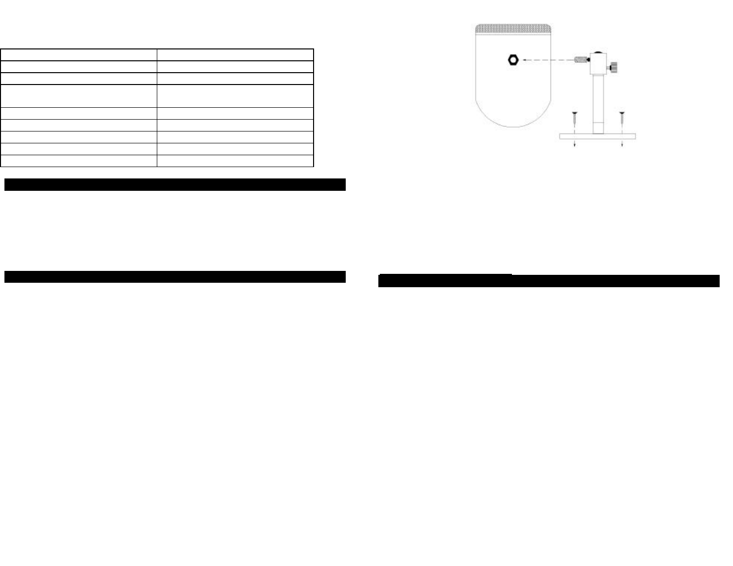
The MNC unit is designed with a swivel joint between the two speakers.
Each speaker can be aimed individually. The unit also comes with a
mounting bracket for attachment to a wall or ceiling. The bracket screws into
the threaded socket on the bottom of the unit, and may be adjusted so that
the speakers point in the desired direction. (See figure 1)
Note: When mounting speakers from wall surfaces additional tightening of
the hex screw may be required.
SPEAKER CONNECTONS
1. Turn off the receiver or amplifier and unplug it from the power outlet.
2. Use a 2-conductor 16-gauge speaker wire (M&S part number MS16X)
for best results.
Note: Remove about 2 inches of the outside jacket from both ends of the
wire then strip approximately ½ inch of the insulation from each conductor at
the speaker end. Use the recommended strip length as specified in the
amplifier/receiver installation manual for the other end.
3. Proper connection of the speaker wire is very important to ensure full
range sound. Most amplifiers and speakers use red (for +) and black
(for -) as the polarity markings. Using the MS16X wire makes connections
easy. The red wire should be connected to the red terminal and the black
wire to the black terminal at the speakers and the amplifier.
Note: When using another type of wire, such as a flat ribbon, you will
need to determine how the wire denotes one lead from another. This usually
takes the form of a rib or a color stripe in the insulation.
4. Repeat these steps for connection of all speakers to the system. Typical
diagrams are shown for the MNC and MNCS systems. (See figures 2
through 4.)
Figure 1
2 of 7
3 of 7
 Manymanuals.com
 Manymanuals.de
 Manymanuals.fr
 Manymanuals.it
 Manymanuals.pl
 Manymanuals.cz
 Manymanuals.es
 Manymanuals-pt.com
Comments to this Manuals